Document
Warning and declaration of conformity
This document refers to the device PANPHONE IP CSIP V6.
For questions about installation, configuration or operation, use the form included in the Contact and questions section.
Use of the document. Reproduction of this manual in whole or in part without authorization is prohibited.
The manufacturer reserves the right to make hardware or software modifications to the device described in this document. Available functions may vary depending on firmware version, activated licenses, installed modules and device configuration.
Statement.
The manufacturer declares that PANPHONE IP products comply with the essential requirements applicable to radio equipment and telecommunications equipment, in accordance with the corresponding regulations.
Documentary support.
For copies, document updates or specific regulatory information, consult the official channels of the supplier or person responsible for the installation.
Contents
General index
1. Introduction
5 subpoints ▼General description, features, preliminary information and CSBOX formats.
2. Installation, assembly and connection
10 subpoints ▼Models, assembly, connectors and relays.
3. Programming and first access
6 subpoints ▼Web access, credentials and menu.
4. SIP accounts
4 subpoints ▼SIP accounts, PBX registration and whitelist.
5. Connectivity
6 subpoints ▼Ethernet, WiFi, 4G, utilities and VPN.
6. Multimedia
5 subpoints ▼Audio, video, RTSP and voice prompt settings.
7. Relays and accesses
8 subpoints ▼Openings, PIN, RFID, QR and schedules.
8. Keypad / Push Button
5 subpoints ▼Keys, dialing, LEDs and inputs.
Activation of modules and extra functions.
10. Tools
4 subpoints ▼Test calls, backup, restart and API.
11. Users
1 subpoint ▼User, language and security management.
12. OPTO board
4 subpoints ▼Auxiliary inputs and third relay.
13. Mounting accessories
3 subpoints ▼Frames, covers and measurements.
14. Technical data
7 subpoints ▼Hardware and audio specifications.
Common questions and diagnosis.
16. Contact and inquiries
1 subpoint ▼Technical support form.
1. Introduction
Welcome to the PANPHONE IP CSIP V6 manual. This equipment is part of a line of communication and access control systems aimed at industrial environments, offices, multi-family buildings and facilities where it is necessary to manage calls and openings safely.
1.1 Overview
The PANPHONE CSIP V6 is an intelligent, hands-free IP intercom that can be connected as a SIP extension of an IP telephone switchboard (IP PBX), to a SIP trunk or to another terminal via direct IP call. It can work on a local network or in remote scenarios, depending on the network and communications configuration available at the installation.
The equipment has relays with voltage-free contacts to activate doors, barriers or other external devices, such as lights, sirens or auxiliary systems. Activation can be done during communication, using DTMF codes from an authorized telephone or through access control systems configured on the board.
Programming is done from a built-in web interface of the device. To access it, use a compatible browser from a computer connected to the same Ethernet network or through the access path established by the installer.
The web interface organizes the configuration in the sections Home, SIP Accounts, Connectivity, Multimedia, Relays, Keypad/Pushbutton, Modules and licenses, Tools and Users.
1.2 Main Features
SIP communication
Up to five independent SIP accounts with the main audio codecs, communication via IP PBX, SIP trunk or direct point-to-point call over IP.
Audio and call
Full-duplex audio, auto-answer for incoming calls, signaling tones, pre-recorded audio, echo cancellation and noise reduction.
Sound settings
Independent control of speaker volume and microphone sensitivity, with remote audio test from the web interface.
Video and multimedia
Possibility of video calls with optional camera, image adjustments, recordings, RTSP streaming, LCD screen and voice prompt language selection.
Connectivity
Ethernet connection and wireless communication via WiFi or optional 4G/LTE, as well as network utilities such as Ping, SMTP, SNMP and VPN.
Relay activation
Activation of relays from extensions or telephones that support DTMF, with voltage-free contacts for doors or other external devices.
Access control
Access system using PIN code, RFID cards, QR codes, schedules and access assignment to specific relays.
Histories and logs
History of actions or events, access control history and VoIP traffic log for review and technical diagnosis.
Web interface
Complete device configuration through internal web server, with differentiated menus for network, SIP, multimedia, access, tools and users.
Calls from the web
Make test calls to extension or IP address directly from the configuration interface.
Keypad and push button
Configurable keys, dialing modes, manual dial length, passkey length and status LED settings.
Modules and integrations
Support RS485, API, Modbus, SNMP, OPTO board, third relay, WiFi, 4G/LTE, video, RFID and QR depending on installed hardware, license and configuration.
1.3 Technical characteristics
- Supported audio codecs: G.711 (u-Law, a-Law), G.722, G.726, G.729, GSM and OPUS.
- VoIP protocols: SIP-RTP in accordance with RFC 3261.
- DTMF Detection: RFC 2833.
- Power: 12 Vdc +/- 15%, 2 A, recommended power supply depending on the installation, or PoE 802.3af.
- Two independent 2 A / 24 Vdc relays with voltage-free contacts; optional third relay via additional board.
- Operating temperature: -10 to +55 ºC. Storage temperature: -10 to +55 ºC.
- Mifare 13.56 MHz RFID reader on devices with installed reader.
- QR code reader via camera on compatible devices.
- Integrated video in devices with cameras, with video, recording and streaming functions depending on configuration.
1.4 Data required before configuring
Before starting the configuration, the installer must have the network data, authorized access credentials, SIP information and relay connection diagram. Technical parameters should not be modified without knowing their effect on the installation.
| Necessary information | What is it used for? |
|---|---|
| IP address or device access method | Allows you to enter the web panel to perform configuration. |
| Authorized username and password | Allow access to the web interface. They must be kept and exchanged if they are initial credentials. |
| SIP data | Extension, user, password, server, port, transport and registration type so that the panel can call or register in the PBX. |
| Network data | DHCP or fixed IP, mask, gateway, DNS and VLAN if applicable. |
| Relays and accesses | Identification of each door, barrier, lock or automation connected to each relay. |
| Installed modules and licenses | Camera, RFID, QR, RS485, OPTO, WiFi, 4G/LTE, SNMP, API or other modules available depending on the equipment supplied. |
Important. Access credentials to the equipment must be guarded by authorized personnel. They should not be included in public documentation or shared with unauthorized users.
1.5 CSBOX Formats
The equipment is also available in CSBOX format (plastic or metal box) for installations that do not require the usual front panel. The dimensions of the case are 125 x 93 x 52 (or 42) mm.
| Model | Description |
|---|---|
| CSBOX-P-IP | Enhanced Full Duplex Audio IP-SIP Intercom PCB assembly with Gray plastic case. Speaker output power up to 1W.(*) |
| CSBOX-P-IP-10W | Enhanced Full Duplex Audio IP-SIP Intercom PCB assembly with Gray plastic case. 10W amplifier. Speaker output power up to 10W.(*) |
| CSBOX-P-IP-OPTO | IP-SIP Intercom PCB assembly Enhanced Full Duplex Audio with Gray plastic case + OPTO card. Speaker output power up to 1W.(*) |
| CSBOX-P-IP-10W-OPTO | IP-SIP Intercom PCB assembly Enhanced Full Duplex Audio with Gray plastic case + OPTO card. 10W amplifier. Speaker output power up to 10W.(*) |
| CSBOX-P-IP-10W-BM | IP-SIP Intercom PCB assembly Enhanced Full Duplex Audio with Gray plastic case + MAGNETIC LOOP. 10W amplifier. Speaker output power up to 10W.(*) |
| CSBOX-P-IP-10W-OPTO-4G | IP-SIP Intercom PCB assembly Enhanced Full Duplex Audio with Gray plastic case + extra 4G Module. 10W amplifier. Speaker output power up to 10W.(*) |
| CSBOX-P-IP-10W-CAM | IP-SIP Intercom PCB assembly Enhanced Full Duplex Audio with Gray Plastic Case + USB Camera. 10W amplifier. Speaker output power up to 10W.(*) |
| CSBOX-M-IP | Improved Full Duplex Audio IP-SIP Intercom PCB assembly with Aluminum metal case. Speaker output power up to 1W.(*) |
| CSBOX-M-IP-10W | Improved Full Duplex Audio IP-SIP Intercom PCB assembly with Aluminum metal case. 10W amplifier. Speaker output power up to 10W.(*) |
2. Installation, assembly and connection
The installation of the PANPHONE IP CSIP V6 must be carried out according to the supplied model, the mounting accessory and the installation electrical diagram. Before fixing or powering the equipment, check the wiring route, the location of the connectors, the available power and the destination of each relay.
2.1 Installation models
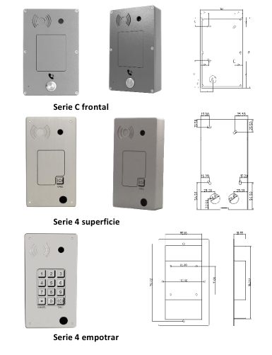
The equipment can be supplied in different installation formats. The assembly procedure depends on the model purchased and the accessory used.
- Front C Series: front format for installation according to corresponding support.
- Series 4 surface: installation with rear cover fixed to the wall.
- Series 4 recessed: integrated installation in a space prepared for the equipment.
2.2 Necessary material
For the basic mechanical installation, at least the following material is required:
- Plugs appropriate to the type of wall or support.
- Screws compatible with the wall plugs and the device base.
- Marking tool, drill and appropriate screwdriver.
- Network, power and opening wiring prepared according to the installation.
2.3 Surface mounting
- Take the base or rear cover and present it in the final position.
- Mark the fixing points on the wall.
- Drill the marked points and place the plugs.
- Route the necessary wiring before closing the assembly.
- Fix the base to the wall with the corresponding screws.
- Install the front panel of the intercom.
- Tighten the security screw located at the bottom of the device.
2.4 Flush mounting
In the built-in model, an approximate gap of 182 x 92mm with a depth of 30mm. Before making the hole, confirm the dimensions of the supplied accessory and leave enough space for the wiring to pass through.
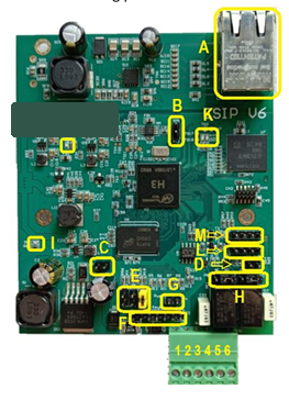
2.5 Identification of internal connections
Before powering the equipment, identify the main connectors on the board. The image shows the location of the internal elements used during connection, configuration and diagnosis.
2.6 Power supply and relay connection
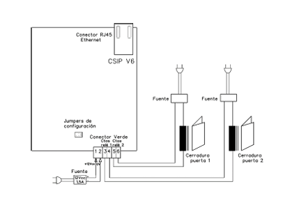
The equipment can be powered by PoE through the Ethernet connector or by an external 12 V DC power supply. The six-terminal connector is used for external power and for the contacts of relays 1 and 2. If the equipment is powered by PoE, it is not necessary to connect external power to terminals 1 and 2, unless specifically indicated by the installation.
| Number | Usage |
|---|---|
| 1 | +12 Vdc |
| 2 | GND / 0 V |
| 3 | Relay contact 1 |
| 4 | Relay contact 1 |
| 5 | Relay contact 2 |
| 6 | Relay contact 2 |
2.7 NO/NC relay contact configuration
The relay contacts can be configured as NO (normally open) or NC (normally closed) using the corresponding jumpers on the board. This configuration must be defined according to the type of lock, door opener, barrier or connected automation.
Caution. Do not exceed the maximum capacity allowed by the relay contacts. If in doubt, use an intermediate relay or consult the installation electrical diagram.
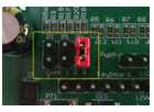
2.8 Equipment Configuration Jumpers
The equipment has a configuration connector made up of three jumper positions. These jumpers are read during device boot. For this reason, any changes must be made with the device turned off and applied when it is turned on again.
| Position | Function | Effect |
|---|---|---|
| Jumper 1 | Temporary access via factory IP | Temporarily assigns the address 192.168.1.50 and allows you to regain access without overwriting stored network settings. |
| Jumper 2 | DHCP | Assigns DHCP to the network configuration. This option overrides the network settings. |
| Jumpers 1, 2 and 3 | Factory Reset | Restores default parameters. The IP is set to 192.168.1.50 and web access uses port 8090. |
2.9 Access Recovery
If it is not possible to access the web interface because the IP address, username or password is unknown, recovery mode can be used using jumper 1. This procedure allows temporary access via the factory IP without deleting the stored configuration.
- Turn off the device.
- Place a jumper in position 1 of the configuration connector.
- Turn on the device.
- Access from the browser to http://192.168.1.50:8090.
- Make any necessary changes to the configuration.
- Turn off the device.
- Remove the jumper from position 1.
- Turn on the device again to return to normal operation.
2.10 Checks before powering up the equipment
- Verify that the equipment is firmly fixed and without mechanical stress on the wiring.
- Check that the Ethernet cable, power and relay contacts reach the connection area correctly.
- Do not power the equipment until you check polarity, voltage and relay connection.
- If PoE is used, confirm that the switch or injector meets the conditions required by the installation.
- If an external power supply is used, check that it provides 12 V DC within the supported range.
- Identify each opening cable before connecting it to the relays to avoid maneuvering on an incorrect door.
Security. The assembly, power supply and connection operations of locks or automation must be carried out by qualified personnel. Do not handle wiring while the equipment is powered.
3. Programming and first access
The configuration of the PANPHONE IP CSIP V6 is done from its internal web interface. To access it, the computer must be on the same network as the device or to the address established by the installer. This first part explains access to the panel, the identification screen, the main menu and the Home screen.
3.1 Browser access
Use a supported browser, preferably Chrome or Microsoft Edge. In the address bar, enter the device's IP followed by the web access port.
- Factory address:
http://192.168.1.50:8090. - If the IP has been modified: use the new address indicated by the installer, keeping the port configured.
- Network range: the computer from which it is accessed must be in the same network range as the equipment, unless there is a route or VPN configured.
Note. If the current IP address is unknown or the credentials do not allow access, use the recovery procedure described in section 2.9.
3.2 Identification screen
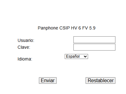
When accessing the device's web address, the identification screen is displayed. From this screen you enter the username, password and interface language.
| Field | Description |
|---|---|
| User | Username authorized to access the web panel. |
| Key | Password associated with the user. It must be kept safe and changed after startup if a default key is maintained. |
| Language | Language in which the web interface will be displayed. The panel language selection does not necessarily replace the language of the audio voice prompts. |
| Send | Validate the data entered and open the configuration panel. |
| Reset | Clears the fields on the identification screen. |
3.3 Initial credentials
The equipment may be supplied with initial factory credentials. These credentials should be used only for the first commissioning and should be changed to a secure password before handing over the installation.
Security. Do not include actual installation credentials in public documentation, work pieces, or screenshots intended for the end customer.
3.4 Main menu
Once the access data has been entered, the panel displays a side menu with the main configuration categories. This menu remains available during navigation and allows you to jump between sections.
| Icon | Section | What is it for? |
|---|---|---|
 | Home | Check the general status of the device: version, date and time, network, jumpers, relays and latest events. |
 | SIP accounts | Configure call accounts, switchboard registration, white list and SIP options. |
 | Connectivity | Configure wired network, WiFi or 4G/LTE if applicable, network utilities, SMTP, SNMP and VPN. |
 | Multimedia | Adjust audio, video, recordings, RTSP streaming, LCD and voice prompts. |
 | Relays | Manage openings, PIN, RFID, schedules, QR, logs, alarms and advanced options. |
 | Keypad / Push Button | Defines the dialing mode, code length, LED behavior and auxiliary inputs. |
 | Modules and licenses | Enables or disables available features depending on installed hardware and license. |
 | Tools | Includes test call, reboot, updates, web server configuration and API. |
 | Users | Allows you to change username, password, panel language and log out. |
3.5 Home Screen
General condition of the equipment
The Home screen shows the version, date and time, network, jumpers, relay status and latest events. The capture must be sanitized before being used in client documentation.
Home screen of the PANPHONE IP CSIP V6 web interface
The Home screen is the first check view. It is not used to program complex parameters; It is used to verify the status of the equipment before continuing with the configuration.
| Data displayed | Utility |
|---|---|
| Current version | Allows you to confirm the firmware version installed on the device. |
| System date and time | It must be correct for schedules, events, logs and temporary access to work properly. |
| Active time | Indicates how long the device has been running since the last boot. |
| Processor temperature | Helps detect abnormal operating or ventilation conditions. |
| IP and MAC address | Identifies the active network connection of the device. |
| Jumpers | Shows the status of the configuration jumpers read during boot. |
| Relay status | Indicates whether each relay appears active or deactivated. |
| Latest events | Summarizes recent events, such as SIP registrations, calls, accesses, or logins. |
Initial check. Before continuing, verify that the version is as expected, the time is correct, the IP corresponds to the installation and the relays appear idle unless there is a test or maneuver in progress.
3.6 First commissioning summary
Use this sequence as a quick guide for a basic installation. Each step refers to later sections of the manual when it requires more detailed configuration.
| Step | Action | Check |
|---|---|---|
| 1 | Assemble the equipment and check the connections. | The equipment is fixed, without mechanical stress on cables and with identified relays. |
| 2 | Power via PoE or approved external power supply. | The board boots and allows access to the web panel. |
| 3 | Access the panel from the browser. | The identification screen is displayed. |
| 4 | Log in with authorized credentials and change the password if applicable. | Access is protected before the installation is delivered. |
| 5 | Review Home, date/time, network, jumpers, relays and events. | No abnormal states appear before configuring calls or openings. |
| 6 | Configure necessary network and connectivity. | The IP, gateway, DNS, WiFi, 4G/LTE or VPN match the installation. |
| 7 | Configure the SIP account or direct call. | Confirm that the account registers or that the point-to-point call works. |
| 8 | Configure relays, PIN, RFID, QR or schedules if applicable. | Each access activates only the intended door or exit. |
| 9 | Make a test call and opening test. | Audio, call, DTMF and relays work correctly. |
| 10 | Log out and document the delivered configuration. | Only the installed, activated and tested functions are noted. |
4. SIP accounts
The SIP Accounts section allows you to configure PANPHONE IP CSIP V6 calls. From this section, SIP accounts, switchboard registration or direct IP calls, the white list of incoming calls and general communication parameters are managed.
4.1 Account overview
Status of available accounts
It is used to see the five SIP accounts on the device, know if they are registered or inactive and enter Configure to edit only the corresponding account.
SIP accounts overview
| Item | What to view or select | Note for configuration |
|---|---|---|
| SIP account 1 to 5 | Select the account to use for installation. | Configure only the necessary accounts. Unused accounts should be left inactive. |
| Registered | The account appears correctly connected to the PBX or SIP service. | This is the expected state after saving and applying a PBX account with network available. |
| Inactive | The account is disabled or does not have valid settings. | If that account should work, open Configure and check username, password, server and network. |
| Name / Ext. | Should display the ID assigned to that account. | It is best to use the actual extension or a recognizable name of the installation. |
| Configure | Press to edit the corresponding account. | Do not change multiple accounts at once; Set up and test one before moving on to the next. |
4.2 Setting up a SIP account
Registration and communication data
The data provided by the switchboard or the network administrator is entered here. If any key field does not match, the account will not register or the calls will not work correctly.
SIP account setup
| Field | What should you put | How to decide |
|---|---|---|
| Enable account | Enabled if that account is to be used. | Must be checked to register or call from that account. Disable it if not used. |
| Registration in PBX or P2P (IP) | PBX if there is a switchboard. IP if you called directly to an IP address. | PBX is common in installations with extensions. IP is used in point-to-point scenarios. |
| Name | Identification name of the account. | Use a clear name to identify the device: main entrance, garage door, reception, etc. |
| User / Ext. | SIP user or assigned extension. | It must match exactly the data in the switchboard. |
| Key | SIP account password. | Copy it without spaces. If registration fails, check capitalization, symbols, and length. |
| PBX domain | Domain or IP of the PBX, if required. | It can be left empty only if the switchboard does not request it. |
| SIP Server 1 | IP or domain of the main SIP server and its port. | The usual port is 5060, unless otherwise configured. |
| SIP Server 2 | Secondary server, if any. | Use only if the installation has SIP support. |
| Transport | UDP, TCP or available option indicated by the switchboard. | UDP is usually common; Always respect the PBX configuration. |
| Audio codec | Preferred codec order for the call. | Select codecs compatible with the switchboard. The equipment allows you to prioritize several codecs. |
| Video codec | Codec supported by the video system, if used. | Only affects devices with a camera or video call; on devices without video it is not a critical setting. |
| Re-registration time | SIP registration renewal time. | Keep the value indicated by the switchboard or the default value if there is no specific requirement. |
| Logging interval | Percentage of registration time returned by the PBX. | Do not change it unless technically indicated. |
Recommendation. Set up one account at a time and check your registration before modifying another. If the account does not register, check username, password, server, port, transport, network and connectivity to the switchboard.
4.3 Whitelist
Incoming call control
Allows you to decide which SIP origins can call the board. It is especially useful when the device is on a network where unwanted calls may exist.
SIP Call Whitelist
| Field | What should you put | When to use it |
|---|---|---|
| Allow all | Select this option if the panel should accept any incoming calls. | Useful in closed and controlled networks, when the switchboard already filters the origins. |
| Lock all | Select this option to reject calls by default. | Recommended when only specific extensions or sources should be able to call. |
| Sender 1 to 10 | SIP address authorized or blocked. | Use one line for each source you want to control. |
| Allow/Deny | Action applied to the entered sender. | Allow authorizes that origin; Deny blocks it. |
| Format | sip:user@address, for example yep:100@192.168.1.50. | The format must match the identifier sent by the switchboard. |
4.4 SIP Options
General communication settings
These parameters affect all SIP calls: network adapter, maximum duration, auto answer, and audio/video port range.
General SIP Options
| Field | What should you put | Note / usual value |
|---|---|---|
| Network adapter for SIP | Select cable, WiFi, 4G or VPN depending on the network output the board should use. | If an option appears as unavailable, the device does not detect that module or connection. |
| Maximum communication time | Maximum duration allowed for each call. | The display allows 0 to 7200 seconds. Use a reasonable limit to avoid open calls indefinitely. |
| Local SIP port | Local SIP signaling port. | 5060 is the usual value. Change it only if the network or PBX requires it. |
| Autoresponder | Manual, automatic or automatic after 1, 2 or 3 rings. | Automatic responds without intervention. Manual requires physical or user action depending on installation. |
| Start RTP port | First port in the range used for audio/video. | Must be allowed on the network and not conflict with other services. |
| RTP port end | Last port in the range used for audio/video. | It must be higher than the initial port and be within the range allowed by the screen. |
Caution. SIP/RTP ports and network adapter directly affect how calls work. Do not change these parameters without knowing the configuration of the switchboard and the network.
5. Connectivity
The Connectivity section groups the device's network configuration and associated tools: wired network, WiFi or 4G/LTE modules when installed, diagnostic utilities, mail sending, SNMP and VPN connection.
5.1 Wired network
Ethernet configuration and network logs
This screen defines the wired network address of the device. It is the main point to leave the board accessible on the customer network and to activate diagnostic logs when necessary.
Wired Network Settings
| Field | What should you put | How to decide |
|---|---|---|
| Current IP address | Value displayed by the device. | Used to confirm which IP is being accessed at that moment. |
| MAC Address | Physical identifier of the network interface. | Useful for DHCP reservations, network inventory or filtering on switches/routers. |
| DHCP | On if the network assigns IP automatically. Off if a fixed IP is configured. | For final installations, a fixed IP or documented DHCP reservation is usually recommended. |
| Static IP address | IP that the board will have when DHCP is disabled. | It must belong to the client's network and not be used by another device. |
| Netmask | Mask corresponding to the local network. | Must match the installation address. |
| Gateway | IP of the router or equipment that outputs other networks. | Necessary for communication outside the local network, remote SIP, mail, VPN or external services. |
| DNS Servers | Primary and secondary DNS. | Required if domains are used instead of IP addresses. |
| VLAN ID | VLAN identifier if the network requires it. Value 0 indicates no VLAN. | It should only be modified if the switch and the client network work with VLANs. |
| Play IP at startup | Activated if you want the device to announce the IP when starting up. | Can help with startup or maintenance when the IP is not known. |
| VOIP SIP Log | Enabled for SIP diagnostics only. | Use the port indicated by the screen and disable it when the test is finished if not necessary. |
| Event log | Enabled if equipment events need to be logged. | Allows you to review operating information from the viewing or download options. |
Important. Before changing the IP, confirm that the new address, mask, and gateway are correct. If an IP is saved outside the network, web access may be lost until the configuration is recovered using the procedure indicated in section 2.9.
5.2 WiFi and 4G/LTE
Configuring wireless modules
The WiFi and 4G/LTE tabs allow you to configure the wireless outputs when the equipment includes the corresponding module. If a tab indicates that there is no device connected, that output should not be used for the installation.
WiFi Settings
4G/LTE Module
When the 4G/LTE module is available, this screen allows you to review the mobile network status and enter SIM and operator parameters. It should only be configured if the board includes the module and the installation uses a mobile connection.
4G LTE Data Settings
| Screen | What to check | Interpretation |
|---|---|---|
| WiFi | Registration status, SSID, key, security type, MAC address, DHCP, static IP, mask, gateway and DNS. | Configure WiFi only if the module is installed and the wireless network has sufficient coverage at the equipment location. |
| Status | Indicates whether the device is registered/connected to the WiFi network. | If Not Registered appears, check SSID, password, security and coverage. |
| SSID | Name of the WiFi network to which the device will connect. | It must be written exactly the same as on the access point. The Search for Networks button helps locate available networks. |
| Password and security | Network password and security mode, for example WPA2. | Must match the actual configuration of the router or access point. |
| DHCP | OnOff | On obtains IP automatically. Off allows you to enter static IP, mask, gateway and DNS. |
| Static IP Address / Mask / Gateway / DNS | Network parameters used when DHCP is Off. | They must belong to the client's WiFi network and not duplicate another existing IP. |
| 4G/LTE | Mobile network status, signal level, IMEI, PIN, APN, username and password. | Configure this data only with a valid SIM and the parameters provided by the operator. |
| Network ID | Indicates whether the mobile module is registered or requires PIN review. | If prompted to check PIN, check the SIM PIN before continuing. |
| Network Type / Level | Shows the available coverage using signal bars. | If the signal is low, check the antenna, location or operator coverage. |
| IMEI | Unique identifier of the mobile module. | It is used for support or registration of the service, it should not be modified. |
| PIN | SIM card PIN, if the SIM requires it. | Must be entered exactly. An incorrect PIN can block the SIM. |
| APN / User / Password | Access data to the operator's mobile network. | Fill them in only with the official data of the operator or the client. |
| SIP Adapter | When a module exists, also check the adapter selected in SIP Options. | The SIP call must go out through the actually available network: cable, WiFi, 4G/LTE or VPN. |
5.3 Network Utilities
Gateway and PING test
This screen allows you to select the network adapter and launch a connectivity test towards a specific address. It is useful to check if the equipment reaches the switchboard, router, SIP server or an external domain.
Network Utilities and Ping Test
| Field | What should you put | What is it for? |
|---|---|---|
| Gateway | Gateway associated with the selected adapter. | Allows you to check or change the network interface used by the device. |
| Network adapter | Cable or other adapter available. | Select the link you want to test. |
| Address | Test destination IP or domain. | Use the IP of the switchboard, the router or a test domain depending on what you want to verify. |
| Perform test | Run the PING test. | The result helps to know if there is connectivity to the indicated destination. |
| Result area | Result returned by the test. | If there is no response, check IP, mask, gateway, DNS, cabling or network rules. |
5.4 SMTP
Sending email from the device
The SMTP setting allows the device to send warning or test emails. It must be filled in with real data from the mail server to be used.
SMTP Configuration
| Field | What should you put | How to decide |
|---|---|---|
| Recipient | Email that will receive the notices or the proof. | It must be a valid address and reviewed by the customer or maintenance. |
| Sender | Email from which the messages will come. | Must be allowed by the SMTP server used. |
| Use server | Internal or external, depending on the installation's mail server. | Use external when the client provides its own SMTP server. |
| Mail server (SMTP) | Domain or SMTP server IP and port. | The port depends on the server. The screen shows port 25 as an example of configuration. |
| User | SMTP authentication user if required by the server. | It must match the configured email account. |
| Password | SMTP account key. | Enter only in facilities where mail delivery is approved and documented. |
| Security | Security mode available in the dropdown. | Select the value required by the mail server. |
| Send test email | Send an email to verify the configuration. | This should be tested before the installation is delivered if mail notices are to be used. |
5.5 SNMP
SNMP monitoring and traps
SNMP allows the equipment to be integrated into supervision systems. It should only be activated when the client has a monitoring platform and provides the necessary parameters.
SNMP Configuration
| Field | What should you put | When to use it |
|---|---|---|
| SNMP Status | Current status of the SNMP service. | Should be checked before documenting active monitoring. |
| Sending traps | On if the device should send traps; Off if not used. | Enable traps only if servers are ready to receive them. |
| Server 1 to 3 | IP or name of the monitoring servers. | Use the servers provided by the customer or network administrator. |
| Community | SNMP community string. | Must match the SNMP platform configuration. |
| Name | Identification name of the equipment. | Use a name that allows you to recognize the location or function of the board. |
| Description | Device description. | Helps identify it in the monitoring tool. |
| Location | Physical or logical location of the equipment. | Identify the location clearly for maintenance: entrance, door, building, floor, etc. |
| Contact | Email or responsible contact. | Use a contact authorized by the customer. |
5.6 VPN
Connection using OpenVPN
The VPN tab allows you to activate an OpenVPN connection by uploading a configuration file and, optionally, a key file. It should only be configured with files provided for that installation.
VPN Settings
| Field | What should you put | Caution |
|---|---|---|
| VPN connection | On to activate the VPN; Off to keep it disabled. | Do not activate VPN without confirming that the files and network are correct. |
| Configuration file (.conf) | OpenVPN configuration file. | Must correspond to the client's installation and VPN server. |
| Key file (.txt) | Optional file with keys or credentials, if required by the deployment. | It must be kept as sensitive information. |
| Save | Applies the selected settings. | Then check that the device maintains access via the expected route. |
Good practices. Always document the final IP, the adapter used for SIP, and any external services configured. Do not leave logs, SNMP, SMTP or VPN enabled if they are not part of the delivered installation.
6. Multimedia
The Multimedia section allows you to adjust audio, video, recordings, RTSP streaming and LCD screen. Some functions depend on the installed hardware, especially those related to the camera, video calling, recordings and display.
6.1 Audio
Levels, buffers, test and language
This screen adjusts the board's audio behavior. Changes must be made with a real call test to avoid excessive volume, low microphone or echo.
Multimedia Audio Settings
| Field | What should you put | How to decide |
|---|---|---|
| Speaker | Speaker output level. | Set this during a real call. Turn up only enough to be heard clearly. |
| Microphone | Microphone pickup sensitivity. | If the caller hears low, increase the value; If there is clipping or noise, reduce it. |
| Echo Cancellation | On or off. | It must be kept activated except for specific technical tests. |
| Audio Buffer | Audio buffer available in the dropdown. | Affects stability and latency. Keep the setup value if the call works correctly. |
| Jitter Buffer | Buffer against network variations. | It can help on unstable networks, but high values can increase the delay. |
| Tolerance | Level used for the audio test. | Use the test to check remote audio without moving personnel to the panel. |
| Voice prompt language | Language or audio mode of the voice prompts. | Select the language for audible messages or disable voice prompts/sounds if the installation requires it. |
6.2 Video
Preview and camera settings
The Video tab allows you to check the live image and adjust camera parameters. The capture includes a reference image in the preview box to clearly show where the camera feed appears.
Multimedia Video Settings
| Field | What should you put | When to play it |
|---|---|---|
| Live Preview | Not populated; shows the camera image. | Used to check framing, visual focus and effect of settings. |
| Brightness | Image brightness level. | Adjust this if the scene looks too dark or burned out. |
| Contrast | Difference between light and dark areas. | Modify this if the image appears flat or has little detail. |
| Saturation | Color intensity. | Use moderate values to avoid artificial colors. |
| Tone | Chromatic correction of the image. | Do not change it unless the image has a color cast. |
| Resolution | 320x240, 640x480 or 800x600, depending on available selection. | Higher resolution offers more detail; Lower resolution can reduce network consumption. |
| Auto White Balance | Enabled for the camera to adjust color temperature. | This is recommended in most installations. |
| White temperature | Manual value if auto balance is not used. | It should only be adjusted when working in manual mode. |
| Backlight compensation | Off or On. | Activate if there is strong light behind the person or object you want to see. |
| Line Frequency | Off, 50Hz or 60Hz. | In European electrical installations, 50 Hz is usually used to reduce flickering. |
| Restore default values | Returns video parameters to base values. | Use this option if the adjustments leave the image incorrect and you need to start from scratch. |
Note. Video settings are saved and auto-applied when moving a control, as indicated on the version 5.9 screen itself. Make small changes and check the preview before continuing.
6.3 Recordings
Conservation and listing of recordings
This screen allows you to define how many days the recordings are kept and consult the available list. If there are no recordings, the table appears empty.
Recording Settings
| Field | What should you enter? | Interpretation |
|---|---|---|
| Days to keep recordings | Number of retention days. A value of 0 disables conservation. | Define it based on customer policy and available capacity. |
| Date/Time | Data shown in existing recordings. | Allows you to locate the time of the recorded event. |
| Destination | Destination associated with the recording. | Helps identify call, access or related event. |
| Type | Type of recording or event. | Used to filter or understand the origin of the recording. |
| Duration | Recorded time. | It should be reviewed if calls or incidents are investigated. |
| Actions | Operations available on recording. | It may vary depending on whether or not recordings are available. |
6.4 RTSP Streaming
RTSP video publishing
RTSP allows you to view the video from compatible systems. It should be configured only if the installation needs to integrate the camera feed into a viewer, recorder, or external platform.
RTSP streaming settings
| Field | What should you put | Caution |
|---|---|---|
| RTSP Streaming | On to activate; Off to disable. | The display indicates that RTSP is not available while the QR reader is active. |
| User | RTSP access user. | Should be known only to authorized personnel. |
| Key | RTSP access key. | Change default values before delivering if the service remains active. |
| Port | RTSP listening port. | The value displayed on the screen is 554; change it only if the network requires it. |
6.5 LCD
Screen Messages
The LCD tab allows you to turn the screen on or off, write two lines of text, and send or clear the displayed content.
LCD Screen Settings
| Field | What should you enter? | What is it for? |
|---|---|---|
| Activate screen | Select On, Off or no change as appropriate. | Controls the status of the LCD screen if the device has one. |
| Line 1 | First text to display. | Use short, clear messages. |
| Line 2 | Second text to display. | Used to complete the message without cluttering the screen. |
| Send | Applies written text. | Check the result on the physical screen of the device. |
| Clear | Clears the displayed content. | Useful when you want to remove a temporary message. |
Final check. After modifying audio, video, RTSP or LCD, make a test call and check image, sound, messages and external services before handing over the installation.
7. Relays and accesses
The Relays section allows you to define how the opening outputs act and how access is authorized using PIN, RFID cards, schedules, QR codes, logs, alarms and advanced options. These settings directly affect doors, locks, automations or auxiliary outputs.
7.1 Relay configuration
Activation mode of each relay
This screen defines how each output behaves. The relays can act independently or through the combined 1+2+3 option.
General relay configuration
| Selectable value | What does it mean? | When to use it |
|---|---|---|
| Relay 1 / Relay 2 | Main opening or maneuver outputs. | Use each relay for a door, lock, barrier, light or other automation defined in the installation. |
| Relay 3 | Third output available when the equipment/hardware supports it. | It should be documented only if the board has this output or additional module. |
| Combined relay 1+2+3 | Joint action of several relays. | Useful when an authorization must activate several outputs at the same time. |
| Timed | The relay activates for a configured time and returns to rest. | Usual mode for opening doors or locks. |
| Manual | The relay is maintained according to manual activation/deactivation order. | Use only when installation requires maintained manual control. |
| During communication | The relay remains active as long as there is communication. | Applicable to maneuvers that depend on an active call. |
| During ringing | The relay activates during the call/ring period. | Use this option only if the automation must follow the incoming or outgoing call status. |
| Press | The relay acts as a pulse associated with an action. | Useful for systems that require short pulse. |
Caution. Before saving changes, confirm that each relay physically corresponds to the expected door or output. An incorrect assignment can open a different door than expected.
7.2 PIN access
Keypad Keys
Allows you to create keypad access keys. Each key is associated with a name, code, time and relay. The screen indicates that up to 250 keys can be entered.
PIN Code Settings
| Field | What should you enter? | Good practices |
|---|---|---|
| Position | Registration number within the list. | Used to organize and locate credentials. |
| Name | Person, home, service or use assigned to the PIN. | Use clear names so you can audit access later. |
| Code | Numeric key to be entered on the keypad. | Do not use obvious or repeated codes. Document who has authorized them. |
| Schedule | Schedule that limits the operation of the PIN. | Select the appropriate time if access should not always work. |
| Relay | Output that will be activated when validating the PIN. | Check that it corresponds to the correct door. |
| Previous / Next | Navigate between key pages. | Use pagination to review all records before submitting. |
7.3 Access via RFID
RFID Cards
Allows you to authorize RFID cards or identifiers. As with PIN, each card is associated with a name, code, time and opening relay.
RFID card configuration
| Field | What should you put | How to use it |
|---|---|---|
| Name | User, home, vehicle or assigned card. | It must allow you to identify who the card belongs to. |
| Code | RFID code of the card or credential. | Enter the exact identifier recognized by the system. |
| Schedule | Card validity schedule. | Useful for maintenance access, suppliers or users with limited space. |
| Relay | Output that will be activated with that card. | Select the corresponding door or maneuver. |
| Save | Applies changes to the current page. | Save after modifying highs, lows or relay/schedule changes. |
7.4 Access times
Time zones
Schedules allow you to limit the operation of PIN, RFID and QR by hours and days of the week. The screen itself indicates that to delete a schedule you must leave the name blank.
Schedule settings
| Field | What should you put | Usage example |
|---|---|---|
| Schedule | Name of the time slot. | For example: Labor, Maintenance, Delivery, 24h. |
| Start / End | Validity start and end time. | Use clear time format and verify that the system time is correct. |
| L M X J V S D | Days of the week when applicable. | Check only authorized days. |
| Blank name | Delete the schedule as indicated on the screen. | Before deleting, check that it is not using active PIN, RFID or QR. |
7.5 Access via QR
QR code generation
Allows you to generate QR codes linked to an operating period and an opening relay. It is useful for temporary access when the device has a compatible reader/camera.
QR access configuration
Configuration of the generated QR
When you press Generate QR, the interface allows you to define name, validity period, time, relay and mailing. This screen completes the configuration of temporary access by QR.
Detailed QR Settings
| Field | What should you put | Caution |
|---|---|---|
| Name | Identification of the generated QR. | Use a name that indicates user, visit, service or purpose. |
| Relay | Output that will activate the QR. | Check that it matches the authorized door. |
| Schedule | Schedule associated with the QR, if applicable. | Useful to limit usage by days and hours. |
| Start / End | Code validity period. | Define expiration dates/times when access is temporary. |
| Temporary | Quick QR duration, for example one hour when that value is selected. | Use this option for short, controlled accesses. |
| Date range | Start and end date and time. | Use this option when the QR must be valid for a specific interval. |
| Send by mail to | Recipient's email address. | Requires SMTP configured and should be used only with authorization from the person responsible. |
| Generate QR | Create the code for use. | Do not hand out QR codes without registering who they are valid for and even when. |
7.6 Access logs
Query, export and delete
The logs show access records and related events. The screen allows exporting in spreadsheet formats and deleting records when appropriate.
Access logs
| Field | Which shows | Recommended use |
|---|---|---|
| Date | Time of registration. | Required to audit incidents. |
| Type | Type of event recorded. | Helps distinguish PIN, RFID, QR or other accesses. |
| Name/Code | Identification associated with the access. | Allows you to relate the event to a credential. |
| Position / Schedule / Relay | Configuration data used in access. | Useful for checking why an output was activated. |
| Export | Download records, according to available icons. | Use export before deleting records if evidence needs to be retained. |
| Delete logs | Delete records based on the selected option. | Do not delete logs without authorization from the person responsible for the installation. |
7.7 Alarms
External alarm due to sensor change
Allows you to send an email notification if the sensor status changes during the set time. The screen allows you to indicate whether the model uses a button or keypad.
Alarm settings
| Field | What should you put | Precondition |
|---|---|---|
| External alarm | On to activate; Off to disable. | Activate only if sensor change warning is needed. |
| Model | Pushbutton or Keypad. | Must match the front/installed equipment. |
| Time | Monitoring time in seconds. | Defines how long the state change is evaluated. |
| Notice email | Address that will receive the notification. | SMTP must be configured correctly in Connectivity. |
7.8 Advanced Options
Cloud and external database
This screen allows you to activate external integrations, such as using the Cloud or connecting to a database. It should only be used in installations that have this integration defined and documented.
Advanced relay options
| Field | What should you put | Caution |
|---|---|---|
| Use CLOUD | On or Off depending on the integration contracted. | Do not activate Cloud if it is not part of the project. |
| External DB | On if an external database is queried. | Requires client-validated server, credentials, and query. |
| DB server IP | Database server address. | It must be accessible from the device's network. |
| Base | Name of the database. | Must match the server configuration exactly. |
| User / Password | Database access credentials. | These are sensitive data and must be safeguarded. |
| SQL QUERY | SQL query to be executed. | It must be provided and validated by authorized technical personnel. |
Delivery to customer. Document which relays open each credential, what hours are active, and who is authorized. Do not provide PINs, cards, QR, database credentials or Cloud configuration without approval from the person responsible for the installation.
8. Keypad / Push Button
The Keypad / Pushbutton section defines how the keypad, pushbuttons, status LED and auxiliary inputs behave. These settings determine whether the user dials extensions, enters PINs, calls contacts, activates relays, or uses external inputs.
8.1 General settings
Device type and default dialing
Allows you to select the front panel operating mode and define how the device interprets the digits entered by the user. In the drawing below, each button or number opens the individual settings for that key.
General keypad and button configuration
| Field | Options/value | Correct use |
|---|---|---|
| Choose type | Keypad / push buttonAuxiliary InputsKeypad + Press relayEarphoneHeadset + keypad | Must match the front and installed accessories. Do not select hardware features that your device does not have. |
| Keypad / push button | Mixed mode for keypad and push button. | Use when the device has a keypad and call/open button according to configuration. |
| Aux Inputs | Gives prominence to the auxiliary inputs. | Use if calls or relays are to be triggered from external contacts. |
| Keypad + Press relay | Combines keypad with push button associated with relay. | Use if the button must act on a relay output. |
| Headset / Headset + keypad | Modes for devices with headsets. | It should only be selected on models that have a headset. |
| Manual dialing digit length | Number of digits that make up a manually dialed extension. | Must match the installation extension length. |
| Password digit length | Number of digits expected for access PIN. | It must match the length of the codes defined in Relays and accesses. |
| Default dialing | Extension DialingPIN dialingAPI Markup | Defines what the device interprets when the user enters digits. |
| Extension Dialing | The digits are treated as extension to call. | Use in installations where the visitor directly dials an extension. |
| PIN dialing | The digits are treated as a password. | Use when the keypad is primarily used for code opening. |
| API Markup | Digits are sent or interpreted using API integration. | Use only if an external integration is defined. |
| Drawing of buttons and numbers | The push-button icon and each keypad digit open their respective configuration screens. | Set each button or key to be used after selecting general mode. |
8.2 Button or key configuration
Action assigned to a button or number
This screen appears when you click on a button or number in the general configuration drawing. Allows you to define what that specific key does. Some options require filling out the extension call block or the direct IP call block.
Push button or key configuration
| Selectable value | What does it do? | Required fields |
|---|---|---|
| Choose type | Simple KeyEnd callCall prefixKey prefixExtension callDirect call to IPManual response | Select the action that key or button should perform. |
| Simple Key | The key remains a simple system action. | No additional call data required. |
| Cancel dialing in progress, End call | Cancel dialing or end a call. | No destination required. |
| Call prefix | Enter a call prefix. | Should be used only if the facility dialing requires it. |
| Password prefix | Enter a password/PIN prefix. | Must match the defined access criteria. |
| Extension Call | Call a PBX extension. | Fill User/Ext. and select SIP Account 1 to 5. |
| Direct call to IP | Call an IP or server directly. | Fill IP, User/Ext. and SIP Account 1 to 5. |
| Manual Answer on Incoming Call | Allows you to use the key to manually answer incoming calls. | Use when the installation requires manual response from the device. |
| SIP account | SIP account 1SIP account 2SIP account 3SIP account 4SIP account 5 | Select a configured and operational account in the SIP Accounts section. |
| SIP account 1 to 5 | Each option indicates which SIP account that key will use to call. | If the chosen account is not registered, the key will not be able to complete the call. |
8.3 Push button contacts
Progressive push call
This screen is opened from the drawing call button. Defines the order of contacts that the device will call. If there is no response within the indicated time, it moves to the next configured contact.
Push button contacts
| Field | What should you enter? | How to decide |
|---|---|---|
| Timeout | Seconds before moving on to the next contact. A range of 3 to 99 seconds is supported in the interface. | Use enough time so that the destination can respond without delaying the sequential call too much. |
| Contact 1 to 4 | Call order. Contact 1 is attempted first; If there is no response, continue with the next configured one. | Sort destinations by priority: reception, concierge, maintenance, etc. |
| Name | Descriptive label for the contact. | Use clear names for maintenance and later review. |
| User / Ext. | Destination extension or user. | It must match the configured switchboard or destination. |
| IP / Server | Destination server or IP. | Use the corresponding SIP server or IP address. |
| Port | SIP port of the destination. | 5060 is common, but the actual installation configuration must be respected. |
| Allow press to hang up | Activated if one press ends the call. | Use if you want the user to be able to end the call from the button. |
| Press delay | Disabled0.5s1s1.5s2s3s | Defines how long the button must be held down before executing the action; Higher values prevent accidental keystrokes. |
8.4 LED Configuration
Visual status indication
Allows you to define how the LED behaves according to the device status: standby, successful registration, outgoing call, incoming call and active communication.
LED Settings
| LED option | What does it do? | When to use it |
|---|---|---|
| Configurable states | Idle, Registration OK, Making call, Incoming call and In communication. | Assign behavior that is consistent and easy to recognize for the end user. |
| Available options | OffPower onNormal flashingFast flashingSlow flashing | The same list can be chosen for each state. |
| Off | The LED remains unlit in this state. | Use if no visual indication is desired. |
| Power on | The LED remains solid. | Useful to indicate idle, successful registration, or stable status. |
| Normal flashing | Intermediate flashing. | Useful for indicating active communication without being too flashy. |
| Fast flashing | More visible flickering. | Useful for outgoing or incoming calls, when you want to attract attention. |
| Slow flashing | Soft flashing. | Can be used for lower priority informational states. |
8.5 Auxiliary inputs
Actions from external contacts
Allows you to configure up to four auxiliary inputs. Each input works as an external trigger: you can initiate a call from a SIP account, send the call to a specific destination and, if applicable, activate a relay.
Auxiliary input configuration
| Item | Options/value | Correct use |
|---|---|---|
| Entry | Entry 1, 2, 3 or 4. | Identifies the physical contact being configured. It must match the actual wiring of the installation. |
| SIP account | SIP account 1SIP account 2SIP account 3SIP account 4SIP account 5 | Select the account from which the call associated with the entry will be made. |
| Destination | Configured extension, user or destination. | Must match the destination that should receive the call or action. |
| Relay | NoneRelay 1Relay 2Relay 3Combined 1+2+3 | Use None if the input should not open or activate output; Select relay only if you must operate an output. |
| None | The auxiliary input does not activate any relay. | Use when the entry should only generate a call or notification. |
| Relay 1 / 2 / 3 | Activates a specific output of the equipment. | It must match the door, lock or control wired to that relay. |
| Combined 1+2+3 | Activates the three relays together. | Use only if the installation requires a documented simultaneous maneuver. |
Check. After changing the type of keypad, LED, auxiliary inputs or pushbuttons, physically test each key and each input to confirm that it calls the correct destination and does not activate unintended relays.
9. Modules and licenses
The Modules and Licenses section allows you to activate or deactivate functions available on the device. These parameters must match the installed hardware, available licenses, and actual installation usage.
Modules loaded
Functions such as API, Modbus, video, RFID, RS485, QR and SNMP are enabled from this screen. Enabling a feature on this screen is not a substitute for the physical module, license, or configuration required for it to function properly.
Modules and licenses screen
| Module | Which enables | When should it be active |
|---|---|---|
| API | Allows you to use integrations or external calls to device functions. | Enable only if the installation uses documented API integration. |
| Modbus | Enables communication with Modbus compatible systems. | Use On if the equipment is part of an industrial or control integration that requires it. |
| Video | Activate functions related to camera, preview, video call or video services. | It must be active when the equipment has a camera or the installation uses video. |
| RFID | Enables RFID card and reader functions. | Activate only on devices with an RFID reader installed and card access configured. |
| RS485 | Enables communication via RS485 bus. | Use On when there is an RS485 connection in the installation. |
| QR | Enables QR code access features. | Must be active if QR codes are to be generated and read. |
| SNMP | Enables SNMP monitoring functions. | Activate only if the client has an SNMP platform and it is configured in Connectivity. |
Important. If a feature is not used, it should remain disabled. Before handing over the installation, verify that only the required modules remain active and that each active function has been tested.
10. Tools
The Tools section groups maintenance and testing actions: test call, reboot, firmware updates, web server configuration, and API options. They are sensitive settings because they can affect remote access, communication or the general operation of the equipment.
10.1 General settings
Test call and reboot
Allows you to check a call from the web interface and perform equipment maintenance actions. It should not be used to restore factory settings unless expressly authorized.
Tools general configuration
| Field/action | Options/value | Correct use |
|---|---|---|
| Test call | Allows you to start a call from the device to check communication. | Use this test after configuring SIP, network, or call destinations. |
| Choose type | Extension Call (PBX)Direct call to IP | PBX calls a switchboard extension. Direct to IP also shows the IP field and is used for point-to-point calling. |
| User / Ext. | Extension, SIP user or test destination. | Must exist on the PBX or the indicated IP destination. |
| Reboot Device | Restart the device keeping the settings. | Useful after changes that require a restart or to recover a blocked service. |
| Restore Device | Restore factory settings. | Critical Action: Clear configurations. Use only with permission and prior copy of necessary data. |
| Automatic Restart | OffEvery 12 hours.DailyWeeklyMonthly | Schedule reboots only if the installation requires it. In normal use it may remain off. |
| Off | Does not schedule automatic restarts. | Recommended option if there is no specific need for preventive maintenance. |
| Every 12 hours. | Restart your device twice a day. | Use only in installations where this policy has been expressly defined. |
| Daily | Performs an automatic restart per day. | Can be used in installations with scheduled maintenance. |
| Weekly / Monthly | Reduces the frequency of automatic reboot. | Select the periodicity indicated by the technical manager. |
10.2 Updates
Firmware and update server
Shows the installed version, update status, update server, and the option to manually upload a firmware file.
Tools updates
| Field | Which indicates | Correct use |
|---|---|---|
| Current version | Firmware installed on the device. The screenshot corresponds to CSIP H6 -- V 5.9. | Used to identify the version before support, maintenance or update. |
| Status | Indicates whether the firmware is updated based on the configured server. | Review this field before manually uploading firmware. |
| Server URL | Server from which the device checks for updates. | Do not change the URL unless instructed by support or the technical manager. |
| Manual update | Allows you to select a compatible firmware file. | Use only correct files for the model and version. Maintain stable power and network during the process. |
Caution. An interrupted update may make the device inaccessible. Before updating, please confirm model, file version, stable power and maintenance window.
10.3 Web server
Web access to the device
Allows you to activate HTTPS and change the access port to the web panel. Any changes to this screen may change the address from which the equipment is accessed.
Web server tools
| Field | Options / value | Correct use |
|---|---|---|
| HTTPS | ActivatedDisabled | Enabled forces encrypted access if the installation supports it. Disabled maintains normal HTTP access. |
| Port | TCP port of the web server. 8090 appears in the screenshot. | If changed, access starts using the new address with that port. Example: http://IP:port/. |
| Save changes | Applies web settings. | Before saving, confirm that you know the new IP and port so you don't lose access to the panel. |
10.4 API
External integration via API
Allows you to configure the API mode, the access key, the IP whitelist, the security level and a notification URL. The key shown in the screenshot has been hidden for security.
API tools with hidden key
| Field | Options/value | Correct use |
|---|---|---|
| API | Indicates whether the API is active. | Depends on the corresponding module/license. If external integration is not used, it must remain disabled. |
| API mode | NormalCustom1 | Use Normal unless the project integration expressly indicates otherwise. |
| Normal | Standard mode of API operation. | This is the appropriate choice for common documented integrations. |
| Custom1 | Special mode reserved for specific integrations. | Do not select it unless the client integration expressly requires it. |
| Token / API Key | Key that authorizes requests to the API. | Sensitive data. It should not be shared in screenshots, emails or public documentation. |
| IP whitelist | One IP per line. | Limits which addresses can use the API. Recommended when the IP of the external system is known. |
| Security level | Token/API KeyIPToken + IP | Token + IP is the most restrictive option when the integration allows it. |
| Token/API Key | The request must include the configured key. | Useful when you cannot limit by IP or when the IP of the external system changes. |
| IP | Authorization is based on the whitelisted IP. | Use only if authorized IPs are fixed and known. |
| Token + IP | Requires valid key and whitelisted origin. | It is the most secure option when the external system has a fixed IP. |
| Notifications URL | External address that will receive notices or events. | Must be a valid URL maintained by the receiving system. |
Security. The API should only be active if a documented integration exists. Protect the token, limit IPs when possible, and test the integration before delivering the installation.
11. Users
The Users section allows you to change the access password to the web panel, select the interface language and close the administration session. It is the last section of the configuration side panel.
User, language and logout
Access to the web panel is managed from this screen. The key must be guarded and changed during startup if a default key is maintained or known to multiple people.
Users screen
| Field/action | What should you put | Correct use |
|---|---|---|
| User | Current web panel user. | Identifies the account under which the device is managed. |
| New Password | New panel access password. | It must be a secure key known only to authorized personnel. |
| Repeat New Password | Repetition of the new password. | Must match the previous field exactly to avoid errors when saving. |
| Save | Save the password change. | After saving, document the new key in the authorized internal procedure, not in the customer manual. |
| Language | EnglishPortugueseSpanishBasqueCatalan | Change the language of the web interface. This setting does not necessarily change the audio voice prompt language, which is set to Multimedia. |
| Change | Applies the selected language. | Use the language required by the installer or maintenance person. |
| Sign out | Close the administration session safely. | Should be used when finishing setup, especially on shared computers or client networks. |
Delivery. Do not include real passwords in screenshots, reports or delivered documentation. Upon completion of commissioning, log out and ensure that access is protected.
11.1 System date and time
The board incorporates a specific date and time setting screen. This setting is important because it affects access schedules, event logs, logs, time codes, and maintenance checks.
| Field/action | What should you put | Correct use |
|---|---|---|
| System date and time | Shows the current date and time of the board. | Should be reviewed before activating schedules, registrations or temporary access. |
| Date type | AutomaticManual | Automatic synchronizes with NTP server. Manual allows you to enter date and time from the panel. |
| Automatic | The board takes the time from an NTP server. | Recommended when the device has a network output to the configured server. |
| Manual | The installer sets the date and time directly. | Use this mode if there is no NTP access or during an isolated startup. |
| NTP Server | Time server, for example en.pool.ntp.org. | It must be accessible from the network configured on the board. |
| Time zone | Installation time zone. | For mainland Spain, select Europe/Madrid. |
| Manual date/time | Date and time entered by the installer. | Only applies when the date type is Manual. |
| Save | Applies the time settings. | After saving, verify that the time is correct in Home and in the logs. |
Review. If events appear with incorrect times or access times do not act when they should, first check time zone, date mode and NTP server.
12. OPTO additional board
The OPTO add-on board is an optional accessory for installations requiring auxiliary inputs and an additional relay output. This section should only be applied when the OPTO board is physically installed in the equipment.
12.1 Identification of terminals and jumpers
OPTO board, inputs and relay 3
The image identifies the auxiliary inputs, ground, reference positive, relay 3 contacts and jumpers JP1/JP2. The selection of internal or external power must be decided before wiring the inputs.
OPTO board with inputs, jumpers and relay 3
| Terminal / element | Indicated function | Correct use |
|---|---|---|
| 1 to 4 | Input 1, Input 2, Input 3 and Input 4. | Connect the external contacts that must be detected by the board here. |
| 5 | GND. | Ground reference for input wiring according to the diagram used. |
| 6 | +V. | Positive input power reference. |
| 7 and 8 | Relay 3 contacts. | Voltage-free output for the additional maneuver defined in the installation. |
| JP1 and JP2 | Power selection jumpers. | Connected: internal power. Disconnected: external power. |
| NO/NC jumper | Relay output selection as normally open or normally closed. | It must be adjusted to the type of lock, barrier or automation connected. |
12.2 Input power supply
The OPTO board supports two ways to power the inputs. The choice depends on the type of signal available in the installation and must respect the connection diagrams of the board.
| Mode | Status of JP1 and JP2 | Indicated power |
|---|---|---|
| Internal power | JP1 and JP2 connected. | 5V (+V). It corresponds to scheme 1 of the image. |
| External power | JP1 and JP2 disconnected. | 5-24V and GND. It corresponds to scheme 2 of the image. |
Caution. Do not mix internal and external power in the same configuration without checking the electrical schematic. With the equipment powered, no jumpers or terminals should be manipulated.
12.3 OPTO wiring check
Before proceeding to the equipment configuration, check that the physical wiring of the OPTO board matches the installation diagram. This point does not replace the configuration of auxiliary inputs in the Keypad / Pushbutton section; It only confirms that the additional board is connected correctly.
| Check | What to check | Expected result |
|---|---|---|
| Entries 1-4 | Each external contact must go to the intended input terminal. | The physical entry matches the installation layout. |
| GND and +V | The power reference must correspond to the chosen mode. | Do not combine internal and external power. |
| JP1 and JP2 | Check if they are connected or disconnected according to the scheme used. | JP1/JP2 connected for internal power; disconnected for external power. |
| Relay 3 | Terminals 7 and 8 must only go to the planned maneuver. | Relay 3 is not used if it is not wired and documented. |
| NO/NC | Check the position of the relay output jumper. | The contact remains normally open or normally closed depending on the lock or automation. |
12.4 OPTO Functional Test
- Verify that the OPTO board is installed and that the equipment is de-energized before handling it.
- Check if JP1 and JP2 should be connected or disconnected according to the chosen power mode.
- Check that each physical input corresponds to the function intended in the project.
- Test each input individually and confirm that it calls the correct destination or activates the intended maneuver.
- Test relay 3 only if it is wired and part of the installation.
Delivery to customer. Document which OPTO input has been used, which physical contact activates it, whether it works with internal or external power and which relay or destination is associated.
13. Mounting accessories
This section includes dimensional assembly references for the indicated series. The dimensions should be used as an installation guide and physically verified before drilling, machining or preparing the recess opening.
13.1 C Series, gray rear
C Series back cover
Use this reference to locate the fixing points and check the available space before installing the equipment on the intended surface.
Series C rear mounting drawing (grey)
13.2 Surface Series 4
Surface Series 4 back cover
The surface back cover is used when the equipment is fixed directly on a wall or stand. Check the dimensions of the fixing points and cable outlets before marking.
Series 4 surface-mounting drawing
13.3 Series 4 for recessing
Series 4 frame for recessing
The recessed frame requires preparing the hole and checking depth, cable passage and fixings before placing the front of the intercom.
Series 4 flush-mounting drawing
Before installing. Always check the physical model supplied, the type of box, the orientation of the front and the cable passage. Do not drill or machine until you confirm that the dimensions correspond to the installed accessory.
14. Technical data
This section contains the technical sheet of the PANPHONE IP CSIP V6. The base corresponds to the technical characteristics of the CSIP V6 board and is completed with the functions visible in version 5.9 of the web panel.
CSIP V6 board and optional OPTO board
The image shows the CSIP V6 board, the RJ45 Ethernet/PoE port, the relay area, the 12 Vdc power supply, the dimensions of the main board and the 42 x 42 mm OPTO auxiliary input PCB.
CSIP V6 board, dimensions and optional OPTO board
14.1 Communication and buttons
| Feature | Technical data | Observation |
|---|---|---|
| Communication protocol | SIP 2.0 compliant with RFC 3261. | Allows you to register the device in an IP PBX or make direct calls over IP according to configuration. |
| Buttons / keypad | A call key or 12-key keypad: 0-9, # and *. | Depends on the front installed. The configuration is done in Keypad / Pushbutton. |
14.2 Audio
| Feature | Technical data | Observation |
|---|---|---|
| Microphone | 1 electret. | Sensitivity is adjusted from Multimedia > Audio. |
| Speaker | 2 W, 8 ohms. | Volume is adjusted from Multimedia > Audio. |
| Audio improvements | Echo cancellation and ambient noise reduction. | Helps improve hands-free conversation in noisy environments. |
| Audio Mode | Full duplex. | Allows you to talk and listen simultaneously during communication. |
| Sound pressure | 77.5 dB at 1 kHz / 1 m. | Speaker reference value. |
| Audio codecs | G.711a/u, G.722, G.726-32, G.729, GSM and OPUS. | Codec priority is configured on each SIP account. |
14.3 Electrical properties, consumption and network
| Feature | Technical data | Observation |
|---|---|---|
| External power | 12 Vdc +/- 15%, 2 A. | Recommended power supply for continuous use. |
| PoE Power | PoE IEEE 802.3af (Class 0, 12.95 W max). | Allows you to power the equipment directly through the RJ45 network cable. |
| Consumption at rest | 100 mA (~1.2 W at 12 Vdc). | Equipment waiting, registered and in service. |
| Call consumption | Maximum 350 mA (~4.2 W at 12 Vdc). | During active conversation with standard speaker. |
| Consumption with amplifier 10 W | Up to 1 A (~12 W peak at 12 Vdc). | In versions equipped with a 10 W amplifier stage at maximum volume. |
| LAN interface | RJ45, 10/100 Base-TX with Auto MDI-X. | Direct connection to local Ethernet network. |
| Relay contacts | 2 NC/NO relays, max. 24 V / 2 A DC, 120 V / 2 A AC. | Free of tension. Optional third relay via OPTO board. |
14.4 Supported protocols
| Protocol/service | Availability | Usage |
|---|---|---|
| SIP 2.0 | Supported. | SIP registration and calls. |
| UDP / TCP | Supported. | Communications transport according to configuration. |
| RTSP | Supported on devices with video. | Camera streaming with user, password and port. |
| HTTP / HTTPS | Internal web server; HTTPS configurable in Webserver. | Authorized local or remote access to the configuration panel. |
| MODBUS | Available as a module/license. | Integration with external systems or SCADA. |
| RS485 | Available as a module/license. | Serial communication in compatible installations. |
| SNMP | Available as a module/license. | Supervision and sending of traps. |
| DHCP | Supported. | Automatic IP assignment. |
| NTP | Supported. | Automatic date and time synchronization. |
14.5 Dimensions, processor and mechanics
| Item/Feature | Dimensions / Data | Observation |
|---|---|---|
| Surface Series 4 dimensions | 185 x 105 x 31mm | Wall mount with back cover included. |
| Dimensions Series 4 for recessing | 216 x 128 x 8mm (Front) Embedded hole: 182 x 92 x 30mm | Built-in wall installation with recessed box or frame. |
| C Series Dimensions (Front) | 175 x 100 x 30mm approx. | Frontal format for mounting on columns or specific supports. |
| CSBOX format dimensions | 125 x 93 x 52 (or 42) mm | Closed plastic or aluminum metal box. |
| CSIP electronic board dimensions | 100 x 85mm | Dimensions of the main board without casing. |
| OPTO auxiliary board dimensions | 42 x 42mm | Optional expansion card. |
| Processor | Allwinner Tech SoC H3, 4 ARM Cortex-A7 cores up to 2 GHz. | High-performance architecture of the CSIP V6 board. |
| Operating temperature | -10 ºC to +55 ºC. | Suitable for indoor and outdoor installations depending on the envelope. |
| Relative humidity | 10% to 95%, no condensation. | Supported environmental range. |
14.6 Special Features
| Feature | Availability | Observation |
|---|---|---|
| Remote opening by dial code | Yes. | Allows you to open from an authorized extension or external telephone. |
| Voice messages | Yes. | Messages such as open door or making a call; They can be customized and configured in different languages. |
| Integrated relays | 2 independent relays. | Voltage-free contacts configurable as NC or NO. |
| Input for push button or external sensor | 1. | Input available on the motherboard depending on model and wiring. |
| Wiegand Mifare Port | 1. | For compatible proximity or biometric sensors. |
| LED indicators | 1. | Waiting, call and communication indication according to configuration. |
| OPTO Expansion Card | Optionally available. | Adds 4 auxiliary inputs and an output relay. |
| DHCP Automatic IP Assignment | Yes. | Configurable from Connectivity. |
| Traffic log control | Yes. | Allows you to review logs from the panel. |
| Local and remote configuration via web | Yes. | Access through the device's internal web server. |
| I/O event notification per SIP call | Yes. | Allows notifications per SIP call depending on inputs and configuration. |
| Integration via API | Optionally available. | Version 5.9 incorporates an API panel with mode, token, IP whitelist, security level and notification URLs. |
| MODBUS protocol | Yes. | Oriented towards integration with SCADA or external systems. |
| RTSP Streaming | Yes, on devices with video. | Configurable with user, password and port. The interface indicates that it is not available while the QR reader is active. |
14.7 Features added or expanded in version 5.9
| Function | Available in panel 5.9 | Where to configure |
|---|---|---|
| System date and time | Yes. | Date/time display: auto/manual mode, NTP server, time zone and manual setting. |
| WiFi | Depending on installed hardware. | Connectivity > WiFi: SSID, key, security, DHCP, IP, mask, gateway and DNS. |
| 4G/LTE | Depending on installed hardware. | Connectivity > 4G/LTE: network identification, level, IMEI, PIN, APN, user and password. |
| VPN | Yes, through OpenVPN configuration. | Connectivity > VPN: .conf file and optional key file. |
| SNMP | Depending on module/license. | Connectivity > SNMP: traps, servers, community, name, description, location and contact. |
| QR | Depending on camera, module and license. | Relays > QR: Temporary QR, date range, schedule, relay and email delivery. |
| Updates | Yes. | Tools > Updates: current version, status, update server and manual update. |
| Webserver | Yes. | Tools > Webserver: HTTPS and port of the web server. |
| API | Depending on module/license. | Tools > API: mode, token/API Key, IP whitelist, security level and notification URL. |
Check. Optional features must match the installed hardware and the status indicated in Modules and Licenses. Do not document as operational a feature that has not been installed, activated and tested.
15. Frequently asked questions
This section includes common installation, start-up and maintenance questions. The answers are designed to help you check the equipment without modifying parameters unnecessarily.
| Question | Answer | Recommended check |
|---|---|---|
| I can't access the web panel. What do I check first? | Check that the device is powered, that the network cable is connected, and that the device is on the same network as the board. | If the IP is unknown, use the jumper recovery procedure indicated in section 2.9. |
| Can I power the device through PoE and an external power supply at the same time? | The equipment supports PoE or external power, but the installation must follow the scheme defined by the technician. | Before connecting, check the power section and confirm if PoE or a 12 V DC power supply will be used. |
| The SIP account does not register. What should I check? | This is usually due to an incorrect user, password, server, port, transport, or network. | Review SIP Accounts and confirm connectivity with the PBX. Also check DNS, gateway and network adapter for SIP. |
| The call connects, but the audio is poor. What should I adjust? | Check speaker volume, microphone sensitivity, echo cancellation, audio buffer and jitter buffer. | Use Multimedia > Audio and make a test call before delivering the installation. |
| The relay does not open the door. Where do I start? | Check that the correct relay is being activated and that the NO/NC contact matches the type of lock or automation. | Check Relays, the terminal diagram and the position of the NO/NC jumpers. |
| When should I use the OPTO board? | Only when the installation needs additional auxiliary inputs or the third relay. | Physically verify that the OPTO board is installed and that JP1/JP2 are in the correct position for input power. |
| Why doesn't WiFi or 4G/LTE appear operational? | Because those functions depend on the installed hardware and the corresponding configuration. | Check Modules and Licenses, and check Connectivity > WiFi or Connectivity > 4G/LTE. |
| Can I use RTSP and QR at the same time? | The interface indicates that RTSP is not available while the QR reader is active. | Define in the project whether QR reading or RTSP streaming is prioritized. |
| What do I do if the schedules or logs appear with the wrong time? | The system date and time should be reviewed. | Set NTP, time zone or manual setting on the Date/Time screen. |
| When should you activate the API? | Only when there is a documented external integration. | Configure token/API Key, IP whitelist, security level and notification URL. Do not share the token in public documentation. |
| What should I check before handing over the installation? | Network, SIP, audio, relay opening, PIN/RFID/QR access, active modules, date/time, credentials and logout. | Leave only the features actually installed and tested documented. |
Support
16. Contact and inquiries
If any questions arise during installation, configuration or maintenance, complete the form indicating as much information as possible about the equipment and the installation.
Recommendation. Do not include passwords, tokens, private keys, or sensitive data in the query. If you need to share network information, do so only through an authorized channel.
Inquiry form
Please indicate the reason for the query so that it can be reviewed by the responsible person.